Network administrators should perform security assessments of hardware that they will provide their users, or particularly paranoid users might want to poke at their devices just to be extra sure.
In this blog post, we will demonstrate the techniques used to assess security on a generic portable router purchased online. We have redacted its identifiable information as our goal here isn’t to provide a free penetration test to the hardware manufacturer. (Someone enterprising enough could still figure this out.)
Can we actually trust this device? This was an inexpensive router, and probably assembled with off-the-shelf components.
In order to assess how secure this device really is, we are going to have to take it apart and figure out what makes it tick.
The packaging
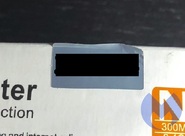
The router came in a small box covered in helpful information about its capabilities, with the only brand attribution being a silver sticker with [REDACTED] written on it.
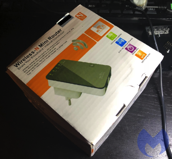
It looks like a device made by a third party and re-branded to quickly bolster the product offerings of another company. A quick Google search did not yield a website for this product on the first page of results, but more digging did reveal a manufacturer that we will not disclose here.
Perusing their product line, we were able to find the router we had purchased. We located a firmware update and downloaded it for further investigation. More on this later.
Gathering equipment
Once we received the router, the first thing we did was disassemble it. The best tool to do this is the ifixit tool kit.
This is the gold standard for disassembling stuff. It comes with many of the esoteric fastener heads devised to frustrate anyone trying to take things apart.
This mini router had no visible screws—this is a trend for many devices as of late. Disassembly required the use of the “spudge tool” from the ifixit toolkit, and we gently pried the cover off. Thankfully, there weren’t any of the warranty “void if tampered” stickers. These are illegal.
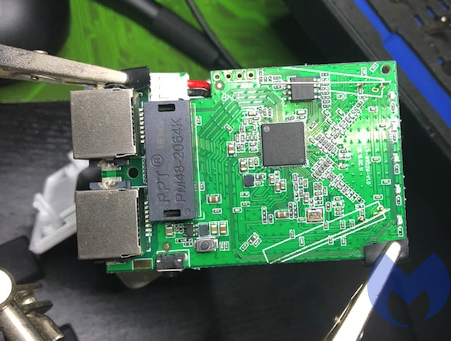
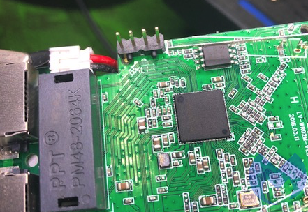
Taking the router apart revealed the main router board with two antennae and one chip in the center. The main chip in the center was an MIPS processor, and there’s a specific model number silk screened onto the mainboard.
Some light Googling revealed that this chipset has a manufacturer website and even a product-specific page.
I also found a WikiDevi page on our exact model. WikiDevi is a user-editable database for computer hardware based on MediaWiki and Semantic MediaWiki. This page contains a ton of good info on the chipset, its capabilities, where it is sold, and by who.
Let’s file those tidbits of information away for now. We’ll come back to them later.
The board has four unpopulated pin holes. These are typically called either “plated-through holes” or “annular rings.” We will just refer to them as plated-through holes for this exercise.
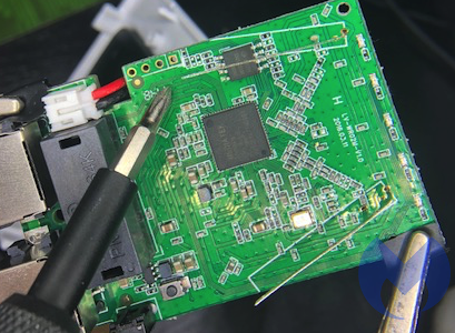
This looks suspiciously like an interface that the manufacturer left on the mainboard. These plated-through holes are usually used to flash the operating system onto the board and test the unit at the factory to verify everything is working properly. There’s no attempt made to hide its purpose.
After some light digging on the product website, we did find mention of the slow I/O features of this chipset.

Further, Googling showed that this pinout is fairly common and might be of the UART variety.
There’s mention of UART on the [REDACTED] product page. This looks promising, like a good place to start. But the plated-through holes are in an awkward position, and examining the mainboard is difficult.
More equipment
In order to get a better look, we did some online shopping. We purchased a “third hand” to hold the mainboard. This portable router is bolted straight to a transformer for the sake of compactness. This means we are in the proximity of 120 Volts, so we should exercise a modicum of caution.
This device is compact and tightly integrated. The chips on the mainboard are pretty small, and our eyesight isn’t what it used to be. Back to the Internet to get a jeweler’s lamp.
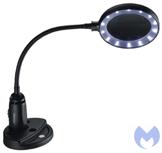
“>
So now we had the magnifying lamp, and it is much better than the little one that comes with the third hand. The LED lights also made examining the main board much easier.
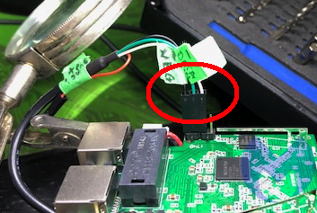
To interact with these pins, we could solder wires in, but we’re planning on using this device, provided it passes muster. This meant we were going to try and be as delicate with our probing as we could. Back to the Internet. After some searching, we found breakaway headers.
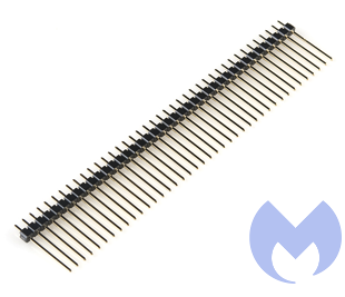
Snapping four off the length make for a perfect pinout adapter. No solder needed, plus easy access for eventually connecting the USB header and for probing the pins.
Shopping
Now we needed to investigate what those diagnostic pins were. Did they have voltage? Were they used to send and receive information? Back to the Internet again for more shopping.Not wanting to buy something too cheap or inappropriate for the task, we Googled affordable voltmeter and found a review for decent and affordable voltmeters. We settled on the Extech EX330 Autoranging Mini Multi-Meter with Built-In Thermometer and Type K Remote Probe.
We also purchased the additional probe connectors kit for good measure. We started with checking for voltage. The bottom half of the router is the transformer. It typically steps down from 120 Volts to 12 Volts. We set the voltmeter to 200 Volts, just to be safe, and got to probing.
Diving in
The bottom plated-through hole had a square about it. Maybe it was special? So we started by applying the ground to it and power to the top pin, and the result was -3.3 Volts. Quickly inverting the probes gave us +3.3 Volts.
Some quick Googling told us that there are two common voltages used in these types of interfaces: 3.3 Volts and 5 Volts. It looks like our router is of the 3.3 Volts variety, the top pin is ground, and the bottom square pin is positive with 3.3 Volts.
So now we knew what the top and bottom pins were. This left the two center pins as a mystery.
Many other much more talented people than us have gone down this particular rabbit hole, and in this, Google was invaluable. We found pictures of other UART interfaces on other routers.
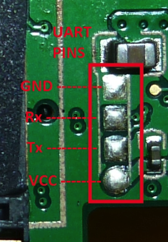
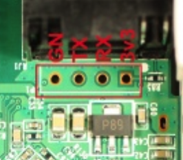
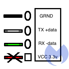
It does not appear that there’s a standardized pin order, but in most of the examples we found online, gnd (ground) and VCC are at the outer edges.
In our case, VCC would stand for “Voltage Common Collector.” More Googling indicated that there is a cable available to interface with these pins and, most importantly, that you don’t need to connect the 3.3 Volt pin unless you want to watch your cable, your router, and potentially your computer go “poof-the-magic-dragon.”
Good to know. Let’s also store this tidbit of information for later.
More shopping
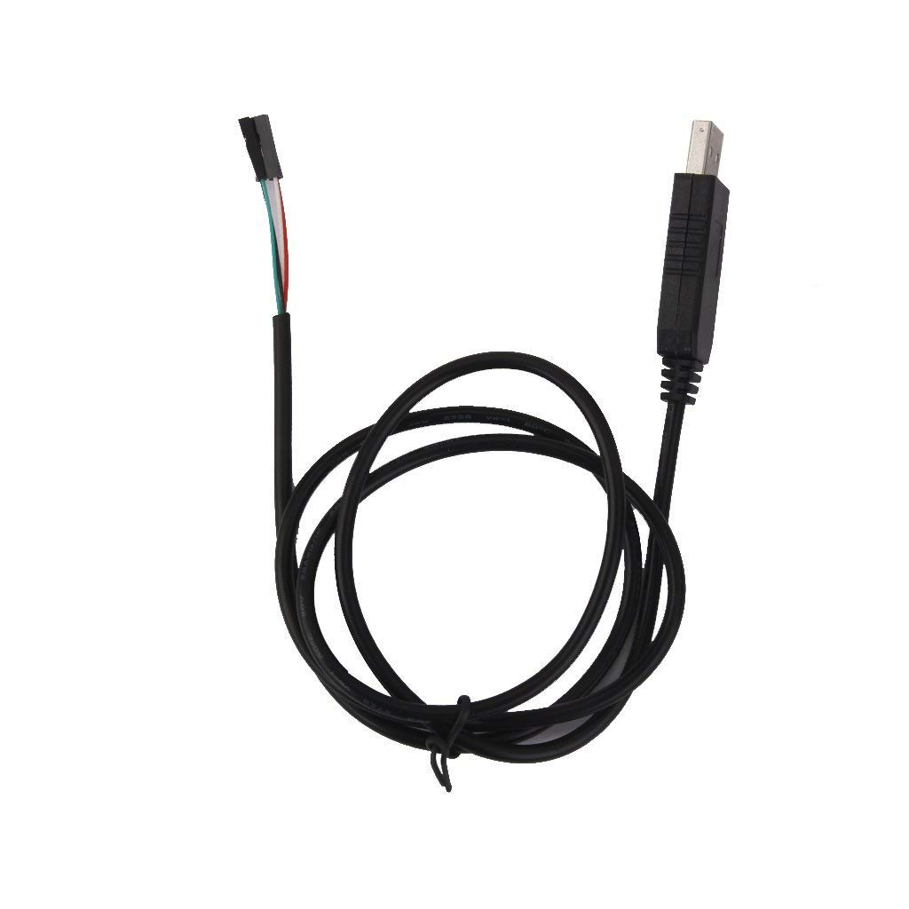
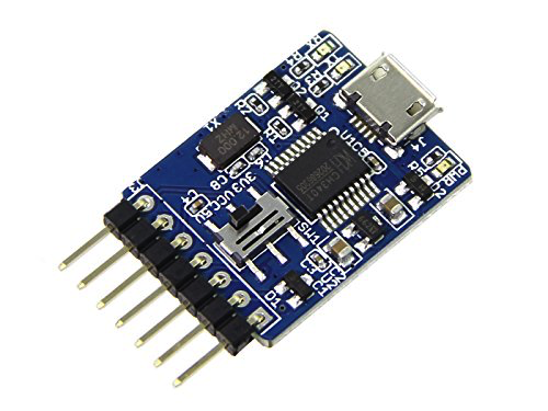
So back to more shopping. We found a USB to RS232 TTL UART PL2303HX Converter USB to COM Cable Adapter Module.
We also found some that specified that they came with both voltage selections and, just to be thorough, we also ordered one of these. It wasn’t available with Prime, so we’re still waiting for this to arrive from the slow boat from China.
Back to the investigation
Not being one to assume anything, we also researched what the color coding was for the cable, as it came in a little bubble wrap with no instructions and sadly nothing in the packaging to indicate whether it was of the 3.3 Volts or 5 Volts variety. Similar USB to UART cables had documentation on the web. We made an assumption and theorized that the cable coloring would be the same as the Google picture results (fingers crossed).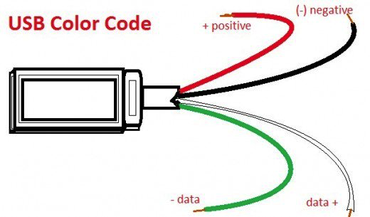
Roadblocks
Colors matched: black for ground, red for power, green for receive, white for transmit. So far, so good. We plugged in the UART to USB cable in our test machine and encountered another roadblock.While it was properly detected and Windows did install the correct drivers, it didn’t work. Some investigation revealed the device could not start.
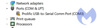
We tried moving the USB device to a different com port in the device manager with no success. We tried downloading the driver directly from the Prolific website and again weren’t met with success. We also tried moving the USB device to a different port (from USB v3 to regular USB). Again, no go.
Digging a little further into the properties of the device revealed that the device cannot start.
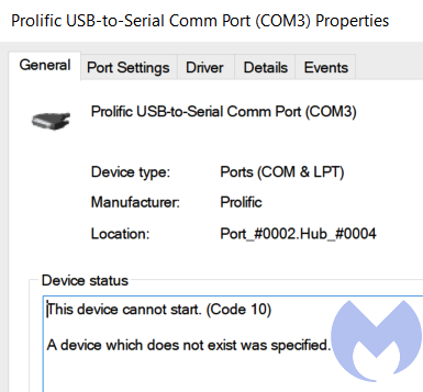
Researching this error yielded this forum post. And more specifically, to this entry:
“Windows 8/8.1/10 are NOT supported in PL-2303HXA and PL-2303X EOL (End Of Life) chip versions.”
So while this USB dongle presumably works, it won’t work in Windows 10. What a surprise! Not to be easily defeated, we rebooted into Ubuntu Linux with the USB dongle still attached.
We then proceeded to check if the USB to serial adapter was working. This is achieved by issuing this command:
$ dmesg | grep tty
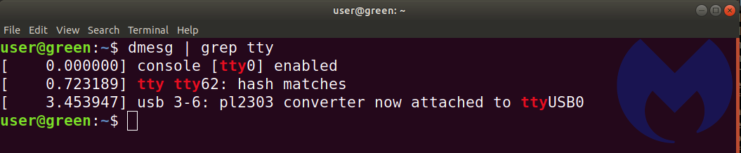
So now we know that the USB adapter is ttyUSB0. The Windows forum mentioned the pl2303 chipset in the adapter wasn’t supported, and we see it here. In Windows, we would’ve used the Putty terminal program. In Linux, we elected to use GtkTerm. It was installed with this command:
$ sudo apt-get install gtkterm
We found that for best results, invoking GtkTerm from bash needed sudo. (We suspect it needed the user account to be part of a group that has permissions to access the ports.)
$ sudo gtkterm
Once gtkterm was running, we needed to select the proper port. We selected the configuration option and opened the port option.
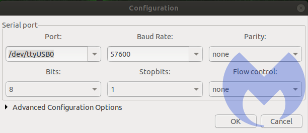
In the port drop-down menu, at the very bottom, we saw /dev/ttyUSB0. This is the Prolific USB adapter.
We left parity bit, stop bit, and flow control to the defaults and hoped for the best.
After this came the tedious task of determining which of the two pins in the center were transmit and receive, as well as the correct baud rate. Our first attempt was gnd, rx tx and vcc unconnected. <-VCC = 3.3V = poof! bad!
These were the results we got. Either TX and RX are inverted, or we have selected the wrong baud rates. There is some kind of communication taking place, but the contents are all garbled. We went through the most common baud rates, but were not met with any success.
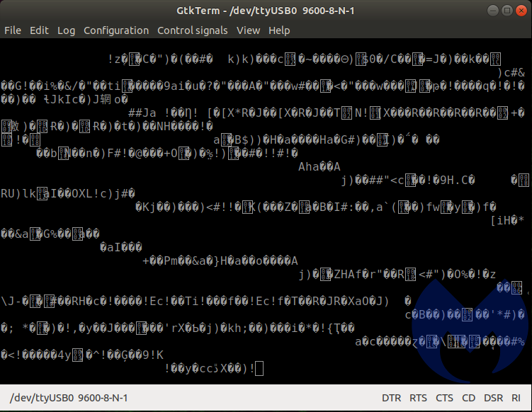
We then flipped the TX and RX and started the process of unplugging and re-plugging the transformer portion of the router, while incrementing the available baud rates in GtkTerm. When selecting the 57600 baud rate, we were met with success!
We could now see how this portable router starts up. It uses u-boot (1.1.3). As the system is starting, there is a brief moment where you are offered options:
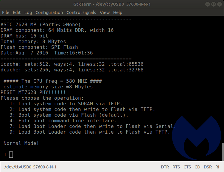
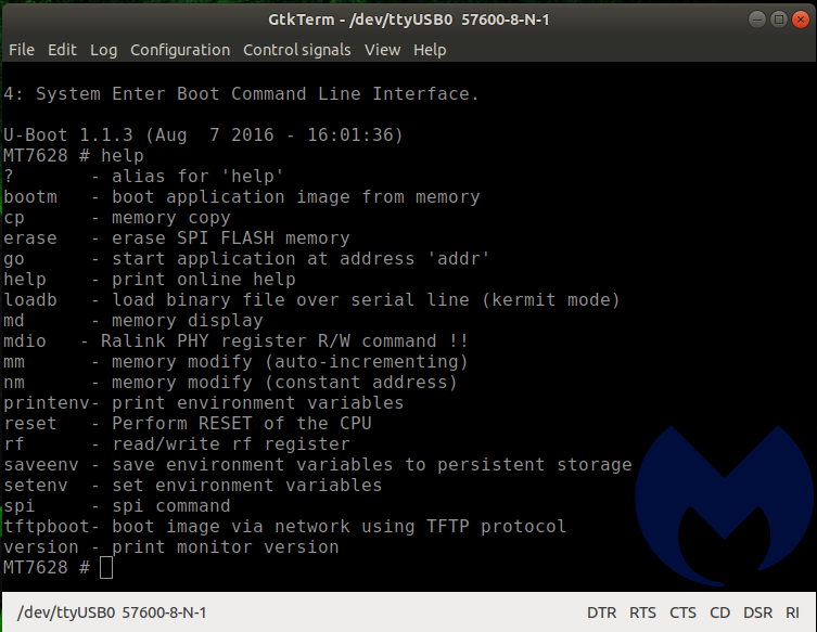
If you enter “4” at just the right moment, it interrupts the boot process and dumps you at a prompt. This is probably the menu used at the factory to apply the correct firmware and perform quality assurance checks and confirm that the unit isn’t defective. Some of the options look like they could be destructive and brick the device, so we were careful in our selection.
Entering “help” gives you a list of the commands available at the u-boot command line.
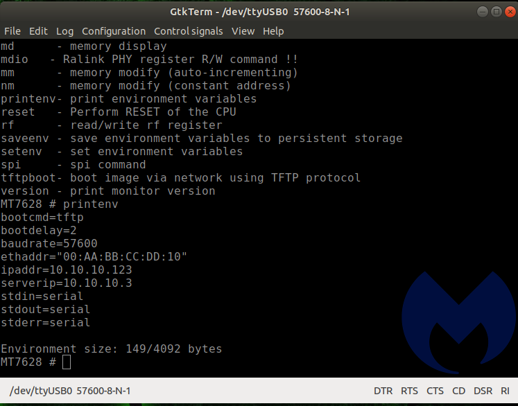
Printenv gives even further information. We could re-flash this unit. We could reset the unit. All of this is good, but doesn’t really help us ascertain the security posture of the device.
We kept navigating the menus looking for interesting things to do, but the U-Boot environment was pretty limited. We also discovered that if you let the boot process take place normally and press any key once it is done, you are dumped at a command prompt as well.
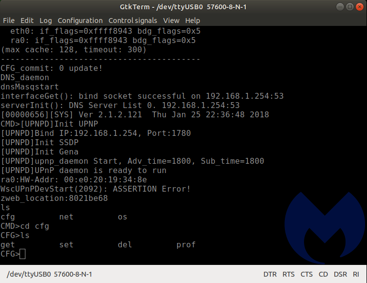
Navigating to the available directories revealed a set of folders: cfg, net, and os. These folders contain files. They are not subdirectories. They don’t have an extension. When invoked individually with no switches, they show a Usage description.
What we learned so far
So what have we learned about the security of this device? Someone with local access could probably modify its behavior quite easily.
The documentation on the chipset mentions that the “[REDACTED] embedded with 8MB memory and provide eCos turnkey for compact router…”
We have a sneaky suspicion that this is the underlying operating system. We know that the U-Boot for MIPS boot loader turns control over to “something” once it’s done initializing the hardware. Turnkey sounds easy, and easy is usually what manufacturers go for.
The wiki for eCos has interesting entries under the “Criticism” heading:
The FreeBSD TCP/IP network stack included with eCos is out of date (circa 2001) and exposes systems to numerous security and stability vulnerabilities (FreeBSD RELENG 4 4 0 RELEASE for IPv4 and FreeBSD’s origin KAME for IPv6). Official eCos maintainers do not appear to monitor FreeBSD or KAME for security or stability updates, but rather rely on minimal and insufficient bug reports from users of eCos.[citation needed]
The SNMP package is rudimentary at best, once again, apparently due to its age.[original research?]
Retrospection
Let’s look at what it has taken so far to gather this information. Some specialized tools, some specialized hardware, some non-trivial computer knowledge, and a certain amount of pig-headedness. And after all this, we haven’t even found anything remotely close to a glaring vulnerability. We know more about our device, and that’s a good thing. However, there’s no way that an average user will go through this. It’s a cool exercise. But it isn’t realistic to expect average users to reverse their devices.
What next?
We want to confirm what the OS is 100 percent and not just rely on a “hunch.” Remember the firmware update we collected from the [REDACTED] website? We’ll try to extract information from the .img file. We are hoping that the update will contain information that is useful. We’re also interested in dumping the local firmware off of the router as well. We’re doing this so we can compare the original firmware with the modified, updated one, as well as to see what was corrected or changed and maybe figure out what was the issue that this update addressed.
Maybe they implemented a fix that only partially fixes the issue? Maybe they fixed the problem and not the underlying vulnerability? All of these questions are worthy of an answer.
Do you see something I’ve done wrong? Have suggestions on other things to try? Reach out to @jean_taggart on the Twitters. I’m keenly interested to hear from all of you.